
I helped my son replace the disc brake pads and rotors on his 1990 4WD Ford Bronco. We quickly discovered that unlike other (non-Ford) cars, the rotors don’t just come off because they are on the inside of the wheel hubs! The first step is to remove the manual or automatic 4WD hubs. Then, the fun begins because you need Ford tool T95T-1197-A to remove the bearing nut. Our Haynes repair manual says we need T59T-1197-A, which I think is a misprint. It doesn’t show a picture of the “business end” of this special socket and the local parts stores don’t seem to have a way to look up Ford tool numbers. So, here is a picture of it:
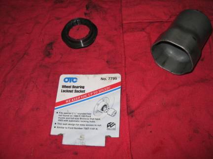
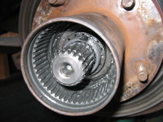
Ford tool T95T-1197-A is equivalent to OTC No. 795. Once we knew what we were looking for, it was available at Baxter Auto Parts. The top of the picture shows the wheel nut. Here is what you’re looking at once the automatic hubs are removed:
1990 Ford Bronco Turn Signal Switch
This procedure requires a steering wheel puller and some patience. The following pictures are for replacing the turn signal switch on a 1990 Ford Bronco XLT with a tilt steering wheel (push on the turn signal lever to tilt). A non-tilt replacement is probably similar, but it uses a different turn signal switch.
Start by removing the two phillips screws at the rear of the steering wheel. You can then lift off the assembly that contains the horn and cruise control buttons. Disconnect the connecter and carefully pull out the ground connection (squeeze the connector to release).
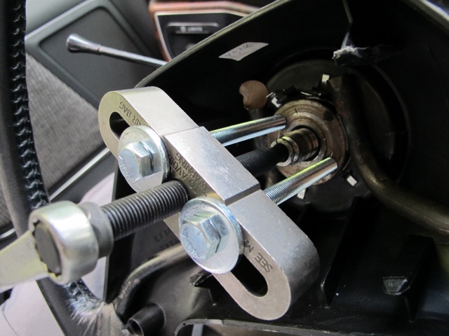
Now, you’ll need a steering wheel puller to remove the wheel. I’m using STL 45000 from CarQuest. The steering wheel came off very easily.
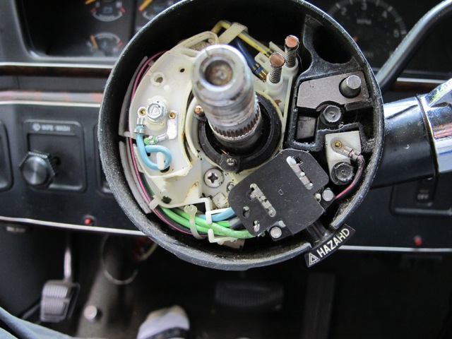
Here is what’s below the steering wheel. You’ll need to remove the two small hex screws on the right and two phillips screws (only one is visible in this picture). Note that the bottom plastic piece which keeps the blinker engaged is broken off.
Disconnect the cable below the dash. You’ll have to remove the connector to pull the cable up the steering column (see next picture). I cut off the wires so that I could use it as a template for new cable/connector. Remove the turn signal switch and pull the cable up the steering column.
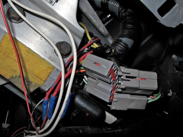
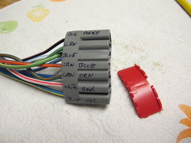
To get the new cable down the steering column, you’ll need to remove the wires from the new connector housing. This is done by removing the red tab from the center of the connector. The pins can now be easily removed with a small screw driver.
At this point, the battery in my camera gave out, so you’ll have to imaging the rest. I taped the wire ends together and attached a wire to help pull it through the steering column. Once it’s down, replace the two phillips screws and two hex screws that hold the turn signal switch in place. Replace the turn signal lever, put the pins back into the connector and connect it under the dash.
When you put the steering wheel back on, make sure you align the mark on the wheel with the one on the shaft.
Updated: January 2017
Contact: GerdHoeren at Gmail dot com